Servo Motor Tester (BLDC Tester)
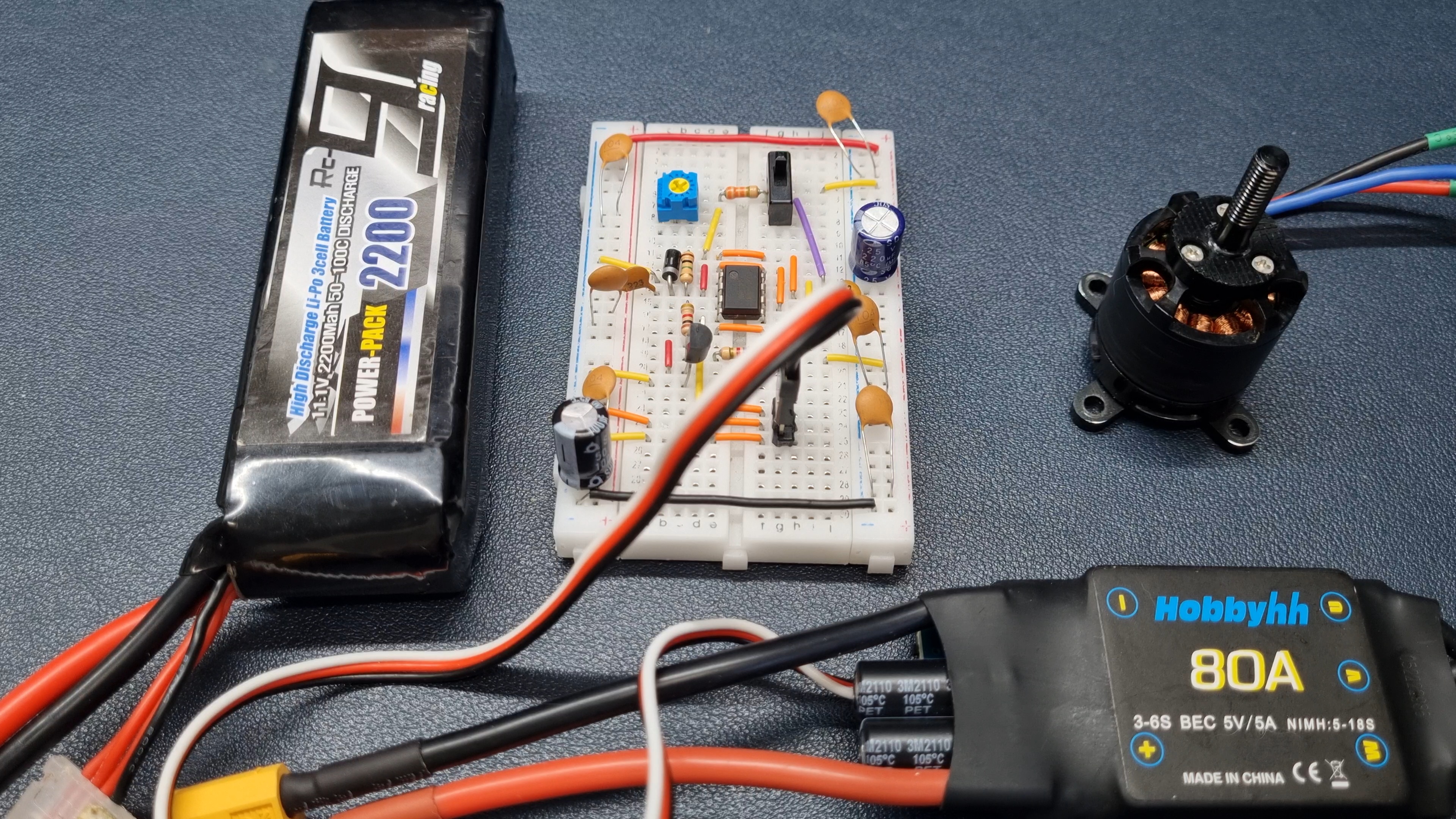
위의 사진은 NE555 타이머를 활용하여 개발한 Servo/BLDC Motor Tester를 나타낸다.
우측의 검정색 모터는 BLDC (Brushless DC) 모터로, 브러시를 사용하는 일반적인 DC 모터와는 달리 브러시 없이 동작하기 때문에 매우 조용한 특징을 가지고 있다.
BLDC 모터는 RC 드론, 비행기의 프로펠러, 헬기의 로터 등에 널리 사용되고 있으며
이 모터는 DC 모터가 아닌 3상 전동기로, 전원 공급을 위한 3개의 케이블로 구성되어 있다.
BLDC 모터를 움직이기 위해서는 Electronic Speed Controller (ESC)가 필요한데 ESC는 3상 모터를 동작시키는 인버터 역할을 수행하여 모터의 속도를 제어하게 된다.
이러한 특성으로 인해 BLDC 모터는 안정적이고 효율적인 성능을 제공하며,
특히 RC 비행체에서는 필수적인 구성품 중 하나로 사용되고 있다.
본인이 제작한 Servo/BLDC Motor Controller의 동작원리는 아래와 같다.
먼저 서보모터와 BLDC의 동작방법은 조금 다른데 DC Servo의 경우 케이블이 총 3개로 이루어져 있다.
흔히 검정,빨강,하얀(제품에 따라 다를 수 있음)색으로 이루어져 있으며 검정색은 GND 빨강색은 VCC 하얀색은 SIG핀으로 사용된다.
검정색과 빨강색에는 모터가 필요로 하는 정격 전원을 연결해주면 되고, 흰색선에는
SIG 신호를 입력해주어야 하는데
대부분의 Servo Motor는 한 주기가 20ms이며 ON_TIME이 1ms~2ms로 동작할 때
Servo Motor가 움직이게 된다.
최근에는 180도 각도로 동작가능한 서보모터 뿐만아니라 270도 혹은 360도의 각도로 동작하는 서보모터가 판매되고 있으며 각도에 따라 전체주기나 ON_TIME은 달라질 수 있으므로 사용하고자 하는 모터의 Datasheet를 활용하면 된다.
위의 회로는 가변저항을 이용하여 모터의 위치를 실시간으로 제어할 수 있는 기능을 가지고 있다.
The above picture shows a Servo/BLDC Motor Tester developed using the NE555 timer.
The black motor on the right is a BLDC (Brushless DC) motor, which has a very quiet feature because it operates without a brush, unlike a typical DC motor that uses a brush.
BLDC motors are widely used in RC drones, propellers in airplanes, and rotors in helicopters
This motor is a three-phase motor, not a DC motor, and consists of three cables for power supply.
An electronic speed controller (ESC) is required to move the BLDC motor, which controls the speed of the motor by acting as an inverter to operate the three-phase motor.
Due to these characteristics, the BLDC motor provides stable and efficient performance,
In particular, it is used as one of the essential components in RC airplanes.
The operating principle of the Servo/BLDC Motor Controller produced by the person is as follows.
First of all, the operation method of the servo motor and BLDC is slightly different, but in the case of DC Servo, there are a total of three cables.
It is often composed of black, red, and white (which may vary depending on the product), and black is used as GND, red, VCC, and white as SIG pins.
Black and red can be connected to the rated power required by the motor, and the white line can be connected to the white line
I need to input the SIG signal
Most Servo Motors operate at 20ms per cycle and ON_TIME at 1ms to 2ms
Servo Motor moves.
Recently, servo motors that operate at 270 or 360 degrees as well as servo motors that can operate at 180 degrees have been sold, and the entire cycle or ON_TIME may vary depending on the angle, so you can use the Datasheet of the motor you want to use.
The above circuit has a function of controlling the position of the motor in real time using variable resistance.

아래의 영상은 가변저항을 이용하여 서보모터의 각도를 제어하는 모습을 표현한 영상이다.
가변저항 값의 변화에 따라 파형의 변화를 확인할 수 있는데 이때 변하는 파라미터는 ON_TIME 이다.
The image below is an image showing a state of controlling an angle of the servo motor using a variable resistance.
It is possible to check the change of the waveform according to the change of the variable resistance value, and the parameter that changes at this time is ON_TIME.
BLDC Motor 또한 동일하다.
BLDC Motor를 동작시키기 위해서는 ESC가 필요하다고 말했는데 ESC에 위의 신호와 동일한 신호를
넣어주게 되면 ESC가 신호를 변환하여 BLDC Motor를 동작시키게 된다.
아래의 동영상은 BLDC Motor의 속도를 변화시키는 모습을 표현한 동영상이다.
대부분의 BLDC Motor는 고속 회전을 하기 때문에 ESC 자체적으로 Lock이 걸려 있는 경우가 대부분이다.
즉,배터리를 연결하였을때 이미 시그널 핀에는 높은 ON_TIME(BLDC 최대출력)이 인가되어 있다고 가정하자.
이런 경우 대부분의 ESC는 동작을 하지 않는다.
안전을 위한 일종의 안전장치라고 생각할 수 있다.
이 문제를 해결하기 위해서는 모터가 요구하는 동작 ON_TIME 중 가장 낮은 ON_TIME을 줬다가 다시 최대 ON_TIME, 그리고 다시 낮은 ON_TIME 순서를 반복하면 Lock이 풀리게 되는데 동영상에서 확인할 수 있듯 ESC에서 발생되는 소리를 통해 Lock 해제를 확인할 수 있다.
Lock 방법은 거의 유사하나 ESC 모델에 따라 약간의 차이가 있을 수 있으므로 해당 ESC의 데이터시트를
참고하기 바란다.
BLDC Motor is the same.
He said ESC is needed to operate BLDC Motor, but he gave ESC the same signal as the above signal
When inserted, the ESC converts the signal to operate the BLDC Motor.
The video below shows how BLDC Motor's speed is changed.
Since most BLDC motors rotate at high speed, ESC itself is often locked.
That is, it is assumed that a high ON_TIME (BLDC maximum output) is already applied to the signal pin when the battery is connected.
In this case, most ESCs do not operate.
You can think of it as a kind of safety device for safety.
To solve this problem, if the lowest ON_TIME among the operations required by the motor is given, the maximum ON_TIME again, and the lower ON_TIME order is repeated, the lock is released, and as can be seen in the video, the lock release can be confirmed through the sound generated by the ESC.
The lock method is almost the same, but there may be some differences depending on the ESC model
Please refer to it.
브레드보드에서 실험을 통해 모터가 정상적으로 동작되는것을 확인한후에 PCB를 설계하여 샘플 PCB로 제작하였다.
브레드보드에서 했던 실험과 동일하게 정상적으로 동작하는것을 확인할 수 있다.
아래의 영상은 PCB를 통해 BLDC를 제어하는 모습이다.
Lock 해제하는 모습또한 영상에 포함되어 있으니 소리를 들어보는것도 좋은 방법일 것 같다.
서서히 ON_TIME을 증가시켜보기도 하고 급격하게 범위를 증감시켜 보았으나 정상적으로
동작하는것을 확인할 수 있었다.
After confirming that the motor operates normally through experiments on the breadboard, a PCB was designed and manufactured into a sample PCB.
It can be seen that it operates normally in the same way as the experiment done on the breadboard.
The image below shows the BLDC being controlled through the PCB.
The image of unlocking the lock is also included in the video, so it would be a good idea to listen to the sound.
I tried to gradually increase the ON_TIME and increase or decrease the range, but normally
I could see that it was working.